Natural Fracture Types
Acknowledgements. This section is an expanded, hypertext version of material presented in the AAPG Geologic Atlas of Borehole Images (Lacazette, 2000), which in turn grew out of unpublished collaborative work with Terry Engelder, Wayne Narr and Manuel Willemse. Because of this history, my friends deserve some credit for this work but I must accept all blame.
About this section. This webpage is a guide to fracture identification that should function like a field guide for identifying different types of animals. The page describes the different types of industrially significant natural rock fractures, their distinguishing characteristics in core, outcrop and image logs, and when complete will provide extensive links to photographs, schematic and example log images, and other information on this and other websites. A flow-chart is provided to help you identify fractures in core, image logs and outcrop.
Fracture classification: The Good, the Bad and the Ugly. The statement "that feature is either a fracture or a fault" is exactly equivalent to saying "that animal is either a dog or a poodle" because fracture is a general term for any type of brittle failure and a fault is a specific type of fracture. So what? Is it really important to correctly identify fractures or is classification just an academic exercise? There are important practical reasons to use correct fracture nomenclature:
- Different types of fractures form in different orientations relative to the earth stresses that prevailed at the time of fracturing. Correctly identifying fracture types is essential for predicting the orientations of fracture populations as a whole and therefore for planning optimum drilling directions and for building reservoir models.
- Different types of fractures have different fluid-flow properties.
- Certain types of fractures form only in specific rock types or in specific geologic environments.
- Certain types of fractures have particular shape/size distributions and obey particular density (spacing) laws which can be used to build 3D reservoir models.
- Geological terminology should remain consistent with fracture terminology in other technical disciplines. Poor usage of geological fracture terminology threatens to create yet more confusing and specialized jargon at a time when interdisciplinary communication is increasingly important. For example, fracture is a general term for a brittle failure of any kind and this usage is consistent between geology and other technical disciplines, such as engineering. The present trend to use the term joint (a natural mode I rock fracture) synonymously with fracture is both confusing and incorrect.
The Way, the Truth and The Light. In the same way that a good biological taxonomy makes it easier to systematically identify animals, practical petroleum geology needs a simple, useful geological taxonomy for fractures. A well developed, reasonably standardized rock fracture terminology that is reasonably consistent with engineering fracture terminology has existed in the structural geology literature for many years. The summarized, organized and simplified version of traditional geologic fracture nomenclature presented here provides practical (industrially useful) fracture classifications. Please use it.
Types of Natural Rock Fractures
Let's define a natural rock fracture as follows:
Fracture. A general term for any non-sedimentary mechanical discontinuity thought to represent a surface or zone of mechanical failure. Chemical processes such as solution and stress corrosion may have played an important role in the failure process. The term is used to describe a natural feature either when available evidence is inadequate for exact classification or when distinction between fracture types is unimportant.
With this definition as a foundation, we can describe the different types of natural rock fractures relevant to the oil industry.
Fracture mode. The foundation of fracture taxonomy is the fracture mode terminology of standard engineering fracture mechanics. Figure 1 shows geologic fracture names in terms of fracture mode terminology. Three fundamental modes of fracture are possible: mode I (mode-one), mode II (mode-two) and mode III (mode-three). All three modes can occur separately or in any combination. Fractures in which two or more modes were operative are termed mixed-mode fractures. For example, a fracture might be termed a mixed mode I-mode II fracture.
Fracture mode nomenclature is purely descriptive, not genetic. For example, a mode I fracture can be formed by one or more mechanisms such as hydraulic fracturing, thermal contraction, and/or diagenetic shrinkage. Stating that a fracture is a mode I fracture only implies that the walls moved perpendicularly away from the fracture plane when the fracture formed.
Figure 1. Fracture mode and geologic fracture names.

Movement sense. The left and right sides of Figure 1 show opposite senses of each mode. Under a given set of conditions, the physical mechanisms of fracture are identical for opposite senses of mode II and mode III failure. However, the two senses of mode I failure occur by different physical mechanisms.
Standard geological fracture terminology is largely based on the engineering terminology, although standard engineering terminology can be used for natural or induced rock fractures. Note that fracture is a general term so that joints and faults are different types of fractures.
Fracture Types and Subtypes
Joint. A natural rock fracture formed predominantly by mode I movement (Engelder, 1987; Pollard and Aydin, 1988). Plumose surface morphology is diagnostic of jointing (Kulander, Barton and Dean, 1979). Unmineralized joints are normally quite permeable. Contained joints are joints that are contained within individual beds of a brittle lithology (Gross, 1993; Gross et al, 1995). The density of contained joints can be quantified precisely using special methods. Two special types of joints are useful because they provide slip-sense, and sometimes slip-direction, criteria for the fault movement. Pinnate joints are a type of joint that forms adjacent to faults during fault movement and/or propagation (Hancock, 1985). Tail joints or wing cracks form at the tip of a propagating fault (Horii and Nemat-Nasser, 1985).
Fault. A type of natural rock fracture formed predominantly by mode II and/or mode III movements. Natural rock fractures that initially formed as joints and were then reactivated as sliding-mode fractures are also termed faults. (Some workers use the term faulted joint.) Faults have a wide range of morphologies and fill types. Faults range from highly permeable to highly impermeable depending on the manner of formation and type of fill. Fault slip-sense and slip-direction often can be determined from surface features. Fault-type names reflect their slip-sense and slip-direction. Fault nomenclature is reviewed here and in standard structural geology texts (e.g. Twiss and Moore 1992).
Fault zone. A fault represented by a zone of intensely deformed rock >1 cm thick. The thickness limitation insures routine application of the term only to zones thick enough to clearly distinguish in image logs. In any specific case, the distinction between a fault-zone and a fault is dependent on the user's interest in the fault rocks and their fluid-flow properties. If these are not of interest then thick fault-zones may simply be termed faults. Similarly, zones thinner than 1 cm may be termed fault zones if fine-scale fracture properties are of interest and the features are distinguishable with the available data. Fault zone refers to the intensely deformed volume of breccia, gouge and/or smear across which most of the slip occurred and does not encompass damage (such as pinnate jointing) in the halo around the fault zone. In other words, material in a fault zone represents disrupted material that is no longer continuous with the parent rock.
Deformation band. A natural rock fracture defined by a zone of grain crushing and compaction developed by mixed anti-mode I + mode II and/or III movement. Deformation bands are cm-scale braided accumulations of crushed zones roughly 0.5–1 mm thick that contain characteristic ramp-and-eye structures. Deformation bands often develop as conjugate sets. They are important to the petroleum industry because they only form in highly porous (>15%) sandstones and chalks (which make good reservoirs) and because the material within a deformation band is about 3 orders of magnitude less permeable than the host rock. Deformation bands cause severe compartmentalization of oil fields in the North Sea, Indonesia, US and elsewhere. (Antonellini and Aydin, 1995a, 1995b)
Compaction band. Compaction bands are unusual features similar to deformation bands. However, they develop by pure anti-mode I movement and may lack the characteristic braided appearance. They can be planar to wavy and may even develop as networks with a mudcrack-like geometry indicating constrictional strain (very rare). Volume loss may be accommodated by extensive grain crushing, in which case compaction bands can be considered a special case of deformation bands. However, some compaction bands develop by grain sliding and rearrangement of grains with little or no crushing so that they do not meet a strict definition of fracture. Compaction bands developed primarily by grain sliding, are rare, and develop only in highly porous (>20%) sandstones having grain sizes of at least 0.3–0.8 mm. (Mollema and Antonellini, 1996)
Stylolite (pressure solution seam). A stylolite (pronounced style-o-light) is a zone of insoluble residue produced by stress-enhanced dissolution. Stylolites typically have a cone-in-cone structure that produces a characteristic zig-zag appearance in cross section. Most geologists do not consider stylolites to be fractures. I used to think the same thing, but I was wrong. Stylolites are fractures! They are stress-corrosion anticracks! Stylolites are correctly termed fractures because:
- They meet the general definition of a fracture.
- Pure anti-mode I deformation bands form by mechanical failure and are generally considered to be fractures. Mode I fractures formed by stress corrosion are considered fractures just as mode I fractures formed by mechanical failure are considered fractures. There is no reason to treat anti-mode I fractures differently from mode I fractures, so stylolites should be classed as fractures.
- A Linear Elastic Fracture mechanics analysis of stylolites shows that simply reversing the signs of the mode I fracture equation correctly describes stylolite development (Fletcher and Pollard, 1981). This indicates mechanical symmetry between opposite senses of mode I failure that is similar to that between opposite senses of mode II and mode III failure. However, in a homogeneous material opposite senses of mode I and mode II failure can occur simultaneously by identical mechanisms under identical conditions of stress, strain rate, fluid pressure, temperature and chemical environment. Opposite senses of mode I failure occur by different mechanisms and under different fracture perpendicular stresses even when both types of fractures develop simultaneously.
Stylolites should serve as flow barriers because the insoluble residue is very fine-grained and clay-rich. However, stylolites are very weak and are easily reactivated as joints by later tectonic events. They are often reported to be permeable in hydrocarbon reservoirs. A slickolite is a type of stylolite in which the teeth are inclined <90° to the plane of the stylolite (Hancock, 1985). Slickolites form at an angle to σ1, often by dissolution along a preexisting fracture. Slickolites are surfaces of shear displacement as well as shortening.
Induced fracture. Any rock fracture produced by human activities, such as drilling, accidental or intentional hydrofracturing, core handling, etc. (Kulander, Dean and Ward, 1990).
1.1.2 - Fracture orientations relative to the principal stress orientations
Earth stress. Stress is defined as the force per unit area acting on a plane. Any stress state at a point in a solid body can be described completely by the orientations and magnitudes of three stresses called principal stresses. The principal stresses are oriented perpendicular to each other and to the three planes of no resolved shear stress at the point. The drawing shows a block of rock having constant stress throughout. The symbol σ (sigma) designates compressive or tensile stress. Subscripts identify specific stresses. The principal stresses are defined: σ1 > σ2 > σ3. Compressive stress and shortening strain are considered positive in rock mechanics and structural geology because in the earth all three principal stresses are always compressive (except around underground voids such as caves or very near to the earth's surface). Joints (extensional fractures) seem paradoxical because they are one of the most common types of natural rock fracture even though they require an effectively tensile driving stress. Pore-fluid pressure drives most joints by producing tensile effective stress through poroelastic loading of flaws that are orders of magnitude larger than typical pores. See Mechanics of jointing for a detailed discussion.
Figure 2. Significance of fracture orientations.
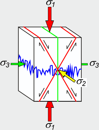
Joints (GREEN). The tip of a growing joint is always perpendicular to σ3 at the joint tip during propagation. Curved joints indicate temporal and/or spatial variations in the orientation of σ3 during joint growth.
Faults (RED). New faults in virgin rock form in each lithology with an approximately constant acute angle between σ1 and the two conjugate fault orientations. This angle ranges from 25° to 40° but is normally about 30°. Pre-existing discontinuities with a wide range of orientations can be activated as faults, provided they are not oriented perpendicular to a principal stress. Deformation bands (faults with an anti-mode I component) also tend to form at 30° to σ1 but can form at any angle <90°.
Stylolites (BLUE) and compaction bands (not shown) form perpendicular to σ1.
1.1.3 - Regional Fracture Orientations
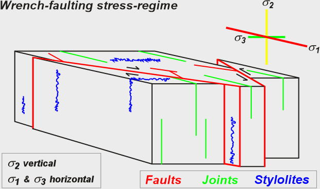
Figures 3, 4 and 5 represent the three most common regional earth stress regimes which are termed the Andersonian stress regimes after the geologist (E.M. Anderson) who first recognized and described them in 1905. In Andersonian regimes one principal stress is vertical so that the other two are horizontal. Be aware that although Andersonian regimes are the most common, inclined stressfields are not unusual. The figures schematically show the average regional orientations in which different types of natural fractures form relative to Andersonian stress regimes.
Figure 3. Normal faulting stress regime.
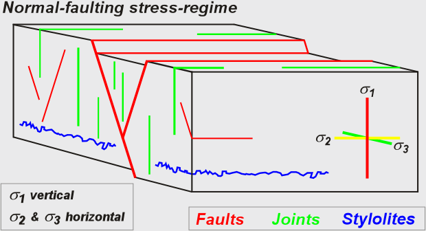
Figure 4. Reverse faulting stress regime.
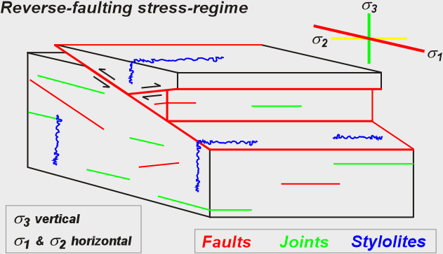
Figure 5. Wrench (strike-slip) faulting stress regime.
Natural fracture orientations are often unrelated to the orientations of the present-day stresses in a rock mass for the following reasons (Engelder 1992):
- Fracture orientation reflects the orientations of the stresses in the fractured rock at the time of fracture formation.
- Regional stress regimes change through time.
- Most natural fractures formed in the geological past under the influence of paleostresses (ancient stresses) that no longer prevail.
The orientation and density of fracture sets may vary with position in a region of interest because stress regimes vary in space as well as in time even if the regional stress maintains a constant orientation. Local stresses may differ significantly in orientation and/or magnitude from regional stresses due to folding, faulting, lithological differences, diagenesis, pore-pressure variations and other influences. (Engelder 1992). For detail on localized fracturing read the following pages on this website:
Fault slip and fault names
This section reviews basic fault nomenclature. If you're already comfortable with fault nomenclature then skip this section and go directly to the Fracture identification flowchart or return to the technical directory to check-out other fun stuff, like fracturing during folding or learn how to avoid making hideous mistakes when you interpret breakouts.
Figure 6 shows the basic fault-slip parameters. The blue arrow indicates the right-hand rule strike, the green arrow dip. The hangingwall is the fault block above the fault plane; the footwall is the fault block below the fault plane.
Figure 6. Fault slip.
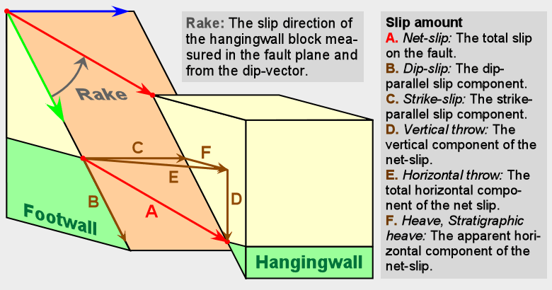
Fault heave and throw can be deceptive because:
- Heave and throw only show one component of fault slip. A fault with a small heave or throw could have a large amount of strike-slip movement.
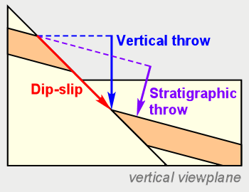
- Vertical throw is very different from stratigraphic throw. This distinction may be very important in directional drilling.
Figure 7. Vertical throw vs. stratigraphic throw.
Basic fault names based on slip direction. Fault names indicate the rake of the movement direction of the hangingwall. Rake is the angle of the hangingwall slip-vector measured in the fault plane from the right-hand-rule strike. Pitch is a synonym of rake. Positive rakes are measured counterclockwise (as seen looking down on the fault plane). Rake can range from +180° to -180°. Figure 8 is drawn looking down on a fault plane. The red line indicates a striation on the fault plane that is parallel to the movement direction. If the hangingwall (the block above the fault plane) moved downwards as indicated by the red arrow, then the rake is -120° and the fault is a right-lateral normal fault. If the block above the fault plane had moved upwards (opposite the direction indicated by the red arrow), then the rake would be +60°.
Right-lateral vs. left-lateral. Imagine that you are standing on one side of a steeply dipping fault as it moves. If objects on the opposite block appear to be moving to your right, then the fault has a right-lateral component. If objects on the opposite block appear to be moving to your left, then the fault has a left-lateral component. The apparent movement is the same whether you are standing on the hangingwall or footwall.
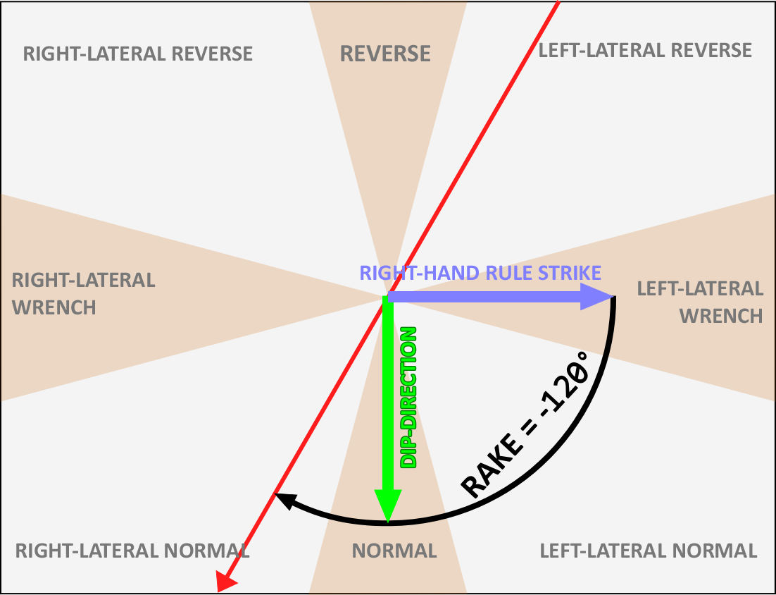
Figure 8. The fault name describes the rake of the slip vector.
Special fault names. Geologists use many different names for special types of faults. These names have complex and far-reaching implications that depend to some extent on the user. When in doubt, use a simple name based on the slip-sense and direction because you will never be wrong and everyone will understand you. Gee, those sound like pretty good reasons to avoid specialized jargon entirely.... Some important types of specialized fault names:
Wrench vs. strike-slip fault. These terms are synonyms and indicate a fault with a slip-vector closely parallel to the fault strike. Some geologists reserve the term wrench for large, regional strike-slip faults, steeply-dipping regional strike-slip faults or as a synonym for tear fault.
Thrust fault. This name once meant any reverse fault with a dip-angle of 30° or less. Now the term indicates faults with an originally low dip-angle that formed during regional compressional deformation. A single thrust fault may change its orientation as it crosscuts different lithologies. Folding can reorient thrusts so that they may have a variety of angles today.
Detachment fault. A regional, low-angle, listric normal fault formed during crustal extension.
Tear fault. Often used to indicate a steeply-dipping wrench fault that bounds or cuts the hangingwall of a thrust or normal fault, also used for mode III faults.
1.1.5 - Fracture Identification Flowchart
The following series of nested charts will help you identify and describe the different types of natural rock fractures. Lists of criteria for identifying features include criteria that are available in image logs and/or core and/or outcrop. All of these features except slickolites and tail joints are identified in image logs under favorable circumstances; however compaction and deformation bands cannot be differentiated from each other in image logs.
To identify and describe a fracture, work through the flowchart from the beginning. Each chart leads to a box that contains a button outlined in blue. Clicking on the buttons outlined in blue is supposed to take you to the next step in the process of classifying and describing the fracture. However, I'm rebuilding this site with an AI that is a bit hard to work with, so all of those buttons don't work yet.
Chart 1: Start
Chart 2: Stylolites
Describe a stylolite or slickolite
In image logs, core or outcrop record the following:
- Orientation (dip-angle/dip-azimuth) of the overall plane of the feature.
- If the feature is a slickolite, then measure the orientation (plunge-angle/plunge-azimuth) of the teeth.
- Maximum tooth height.
- Thickness of fill (insoluble residue).
- Evidence of relative age such as abutting and crosscutting relations.
- Any evidence of reactivation.
Chart 3: Fractures
Describe a natural fracture
In image logs, core or outcrop record the following:
- Orientation (dip-angle/dip-azimuth)
- Evidence of relative age such as abutting and crosscutting relations.
- Overall shape, planarity or any other distinctive feature.
- Any available information on size and shape.
- Host lithology.
Chart 4: Joints
Describe a joint
In image logs, core or outcrop record the following:
All joints:
- Orientation (dip-angle/dip-azimuth)
- Evidence that the feature is a joint. Different evidence is available in image logs, core and outcrop.
- Evidence of relative age such as abutting and crosscutting relations.
- Gross morphology.
- Any available information on size and shape.
In outcrop, sometimes in core:
- Surface morphology.
- Any evidence of reactivation.
Record additional information on joint subtypes:
Contained joints
- Nature and lithology of the feature that contains the joints. In other words, is the joint contained within a single bed, between two older joints, or some other feature?
- Thickness/spacing of bed, strata, or older fractures that contain the joint.
Pinnate joints
- Orientation of parent fault and other relevant information.
- Planarity and any available shape information.
Tail joints
- Orientation and nature of parent fracture.
Chart 5A: Faults
Describe a fault or fault zone
Describing a fault is a four-part process:
- Step 1: Name the fault type based on the slip-sense and slip-direction (Normal, Reverse, Right-lateral wrench, Left-lateral wrench, or compound name).
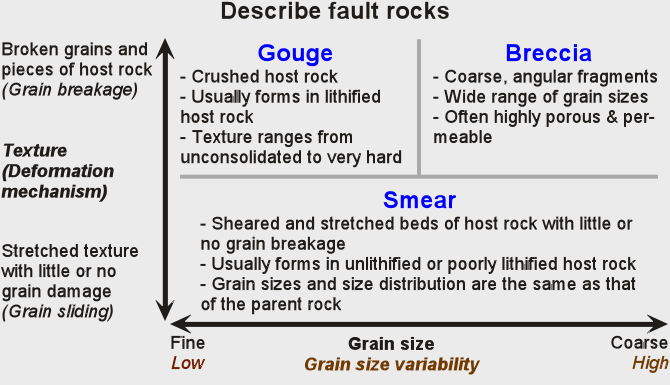
- Step 2: If your fault is a fault zone, describe the fault-rocks.
- Step 3: Record the key characteristics — orientation, evidence of faulting, slip parameters, relative age, thickness of damage zone, gross morphology, size and shape.
- Step 4: Describe the mineral fill.
Describe a compaction band
In image logs, core or outcrop record the following:
- Orientation (dip-angle/dip-azimuth)
- Evidence of relative age such as abutting and crosscutting relations.
- Overall shape, planarity or any other distinctive feature.
- Any available information on size and shape in the plane of the compaction band.
- Host lithology.
- The orientation of sedimentary layering inside and outside of the band, if the layering is visibly deflected.
Fault description - Step 4
Chart 7: Describe the mineralization
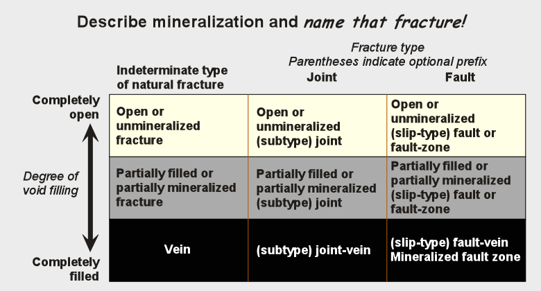
Describe the mineralization
Classify the fill type and name your fracture. Examples:
- Unmineralized reverse fault.
- Partially mineralized contained joint.
- Fracture.
- Partially filled fracture.
- Mineralized, brecciated, fault zone.
Note: deformation bands and compaction bands have very little porosity (<3%) and no large voids so that any cement or mineral fill is not readily visible and isn't described.