Localized fracturing during wrench faulting
Introduction
This page discusses some aspects of fracturing during regional faulting, with emphasis on wrench faulting. This section will be expanded substantially.
Background. This section assumes that you have read the introduction to Section 1.3 and are familiar with:
- Natural fracture nomenclature.
- Fracture orientations relative to the orientations of the principal stresses.
- Regional fracture orientations.
Wrench fault bends
Like any fault, wrench faults can develop bends in a variety of ways:
- The fault may follow, or be deflected by, older faults or other geologic features as it propagates.
- The fault may enter a region of the earth where the stress state, rock properties, and/or pore pressure is different.
- Two non-coplanar faults growing toward each other form a stepover when they interact and hook into each other. A fault may form stepovers on either end. Stepovers will be discussed in detail in sections on fracture mechanics and fault propagation.
Regardless of how a fault bend forms, only two types are possible in 2-dimensions: extensional and convergent, shown respectively in green and red in Figure 1. Extensional and convergent bends are typically the most prominent features of wrench-fault systems. In 3-dimensions a fault can also have bends which are parallel to the slip direction, and bends at a general angle to the slip direction.
Figure 1. Map view of extensional and convergent bends on a right-lateral wrench fault.

Convergent bends develop systems of thrust faults that thicken the rock column while extensional bends develop systems of normal faults that thin the rock column. Analyzing fracture development at wrench-fault bends therefore involves the same types of analysis that are required in normal faulting and thrust faulting environments. The section of the right-lateral San Andreas fault between Los Angeles and the northern end of the Gulf of California provides a classic example of extensional and convergent deformation at adjacent bends on a wrench fault. The Transverse Ranges north of San Diego are mountains developed by thrusting at the convergent northern bend, while the Salton Trough is a basin developed at the extensional bend at the southern end.
Stress regimes at fault bends
During wrench faulting, σ1 and σ3 (the maximum and minimum compressive stresses) are horizontal and σ2 (the intermediate compressive stress) is vertical. In general, the vertical stress at a point in the earth is equal to the weight of the overlying column of rock and, in most cases, the vertical stress is one of the principal stresses. Thrusting develops at a convergent wrench fault bend when lateral contraction of the rock in response to convergence increases σ3 (which is horizontal in a wrench-faulting regime) until it exceeds the vertical stress, in other words, when the vertical stress becomes σ3. Similarly, normal faults develop at extensional bends when lateral expansion due to extension decreases both horizontal stresses until the weight of the rocks becomes the maximum stress, in other words, when the vertical stress becomes σ1.
Secondary structures
Structures characteristic of other faulting regimes can develop during any type of faulting event, so this paragraph can be read as a general comment on secondary structures that commonly develop even when one type of deformation clearly dominates a terrane.
Figure 2 shows a schematic view of an area undergoing wrench faulting. The figure depicts the case of a strong fault — in other words, when the fault is sufficiently strong that it can support a shear stress that is equal or nearly equal to the regional stress away from the fault. Although an inactive fault may be strong, research indicates that active faults, such as the San Andreas fault in California, are probably weak and cannot support large shear stresses. Secondary structures such as normal faults, folds, thrust faults, and joints can form throughout the area when the local stress regime changes similarly to the way it changes at extensional and restraining fault bends. Such changes may result from one or more of the following (and other) mechanisms:
- Temporal far-field stress fluctuations.
- Lateral, vertical and/or temporal changes of rock properties.
- Modifications of the local stress field due to the presence of, or movement on, older structures.
- Regional and/or temporal pore-pressure changes.
Antithetic faults are simply conjugates to the main faults. Any stress regime favors two conjugate fault orientations equally, although one orientation is always better developed. One fault set develops in preference to its conjugate because of regional strain considerations/room problems.
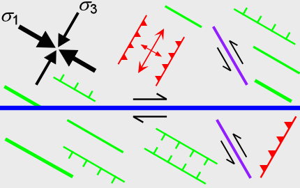
Figure 2 - Legend.
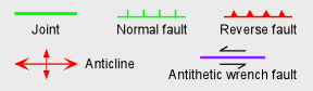
Figure 2. Schematic map view of wrench faulted area indicating the type and orientation of secondary structures that will develop if the friction is so high along the fault that the regional stress field is not affected significantly by fault slip, which is unrealistic in many or most cases.
TO BE CONTINUED. This section will be expanded substantially.