Breakouts and induced fracture basics: Don't make these common mistakes!
Introduction
THE PROBLEM: Many practicing earth scientists are grossly confused about what breakouts represent. These folks think that: (1) the present-day minimum principal earth stress is always horizontal; (2) the breakout axis is always parallel to it so that the breakout azimuth directly tells you the orientation of that stress.
Unfortunately, these ideas are completely wrong except in two special cases. In the general case the breakout azimuth has a complex relationship or no relationship to the orientation of the minimum earth stress.
WHY IT MATTERS: The misconceptions lead to the conclusion that hydrofracs will run perpendicular to the breakout axis. This error can and has resulted in entire oil fields being drilled with the wrong pattern. Many software vendors have written log interpretation software that only reports breakout plunge-azimuth and ignores the plunge-angle of the breakout axis — presenting only the plunge-azimuth is incorrect because breakouts are 3D objects.
Breakout parameters: What to measure
Breakouts are indentations in the wellbore wall that form when present-day earth stresses cause rock failure. Breakouts nearly always form simultaneously on opposite sides of the wellbore.
Breakout orientation is the most important breakout parameter. The breakout orientation is the orientation of the line that connects the centers of the breakouts on each side of the wellbore. Note that the axis orientation is a three-dimensional orientation — it has both a plunge-azimuth (horizontal angle, compass azimuth) and a plunge-angle (vertical angle).
Breakout width is the angle subtended by the breakouts. Breakout depth is the distance from the original wellbore wall to the deepest part of the breakout.
Figure 1. Breakout orientation and width in wellbore cross-section.
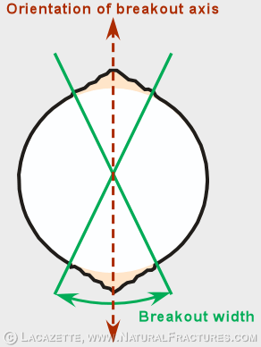
Figure 2. Breakout depth.

Breakouts and induced tensile fractures form at constant azimuths in the wellbore
A breakout orientation DOES NOT necessarily indicate the orientation of the present-day minimum principal compressive stress. Instead it indicates (to a first approximation) the orientation of the minimum borehole-perpendicular component of the present-day stress field.
Figure 3. Wellbore-perpendicular cross section showing breakouts, induced tensile fractures, and stress components.
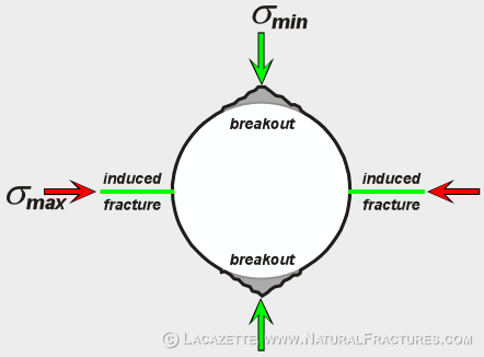
Figure 4. Schematic image log showing geometry of breakouts and induced tensile fractures.
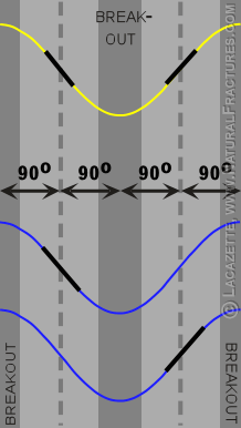
When the minimum principal stress is perpendicular or nearly perpendicular to the wellbore, induced tensile fractures form parallel to the wellbore. When the minimum principal stress is inclined to the wellbore, the tensile fractures are inclined to the wellbore and the relationship between the induced tensile fracture orientation and the principal stress orientations is complex.
The relationship between earth stress and wellbore stress
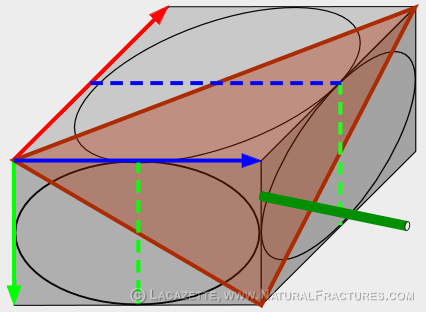
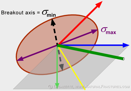
The three principal stresses define a triaxial ellipsoid. Wells drilled parallel to one of the principal stress axes are special cases because the wellbore-perpendicular plane is a principal plane — a plane that contains two of the three principal stresses. In these cases the breakouts reflect the orientation of either the minimum or intermediate principal stress.
A well drilled at a general angle fails in response to the stresses in the wellbore-perpendicular plane. The stresses in this plane are a complex combination of all three principal stresses.
Figure 5. Stress block showing principal stress ellipsoid and wellbore orientations.
A common mistake: Equating breakout orientation with principal stress orientation
The breakout azimuth is the horizontal component of the breakout axis orientation. Note that the breakout azimuth is different from the principal stress azimuths. In the case shown here, the minimum principal stress is vertical so it has no horizontal component and the breakout azimuth reveals nothing about its azimuth. Because hydrofracs always run perpendicular to the minimum stress once they have propagated a few wellbore diameters, any hydrofracs driven from this well will run horizontally, not perpendicular to the breakout azimuth.
Figure 6. The breakout azimuth is different from the principal stress azimuths.
Why are these mistakes so common?
These misconceptions have the following origins:
- Once upon a time all wells were vertical so that breakout azimuths were always horizontal and there was no vertical-angle to be measured for the breakout axis. This is why the logging companies never gave the vertical-angle as output in their software.
- About 60–70% of the Earth's crust is in a normal-faulting stress state in which the minimum and intermediate stresses are horizontal. Another 15–20% is in a strike-slip faulting stress state. So if you randomly sink vertical wells around the world then the misconceptions give correct results most of the time.
- Traditionally, the main use of breakout data was to predict the orientation in which hydrofracs would run. Hydrofracs always run perpendicular to the minimum principal stress, so the misconceptions gave good frac predictions most of the time.
- Petroleum geology was/is dominated by technological expertise developed in the U.S., where most areas are in a normal-faulting or strike-slip faulting stress state.
- Until recently, most geologists, engineers and log-analysts didn't learn geomechanics as part of their university education.
Go to to learn more about regional earth-stress regimes.