Breakouts and induced fracture basics: Don't make these common mistakes!
Introduction |
|
|
THE PROBLEM: Many practicing earth scientists are grossly confused about
what breakouts represent. These folks think that: Unfortunately, these ideas are completely wrong except in two special cases. In the general case the breakout azimuth has a complex relationship or no relationship to the orientation of the minimum earth stress. WHY IT MATTERS: These misconceptions have had serious consequences: This web page reviews key earth-stress concepts and explains the basics of breakout and induced fracture interpretation. |
CONTENTS
Breakout parameters: What to measure |
||
|
Breakouts are indentations in the wellbore wall that form when present-day earth stresses
cause rock failure. The mechanics of breakout formation are discussed on another page of
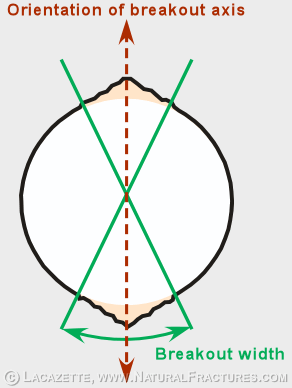
this website. Breakouts nearly always form simultaneously on opposite sides of the wellbore. Although breakouts form over depth intervals, they are measured in wellbore-perpendicular cross-sections at discrete depths. Figure 1 shows such a wellbore-perpendicular cross-section. Breakout orientation is the most important breakout parameter. Figure 1 shows a perpendicular cross-section of a wellbore with breakouts. The breakout orientation is the orientation of the line that connects the centers of the breakouts on each side of the wellbore. Note that the axis orientation is a three-dimensional orientation. In other words, the axis has a plunge-azimuth (the horizontal angle which is given as a compass azimuth) and a plunge-angle (the vertical angle, which is usually measured downwards from horizontal and given in degrees). If your image log analysis software doesn't measure both of these angles (and most packages do not) then you should ask the company that makes it why they are providing you with such a shoddy product. The rest of this webpage explains why it is so important to measure the full three-dimensional orientation of the breakout axis. Breakout width is the angle subtended by the breakouts, as shown in Figure 1. Breakout depth is the distance from the original wellbore wall to the deepest part of the breakout, as shown in Figure 2. |
Figure 1.
|
|
CONTENTS
Breakouts and induced tensile fractures form at constant azimuths in the wellbore. |
|
| A breakout orientation DOES NOT necessarily indicate the orientation of the present-day minimum principal compressive stress. Instead it indicates (to a first approximation) the orientation of the minimum borehole-perpendicular component of the present-day stress field. |
Figure 3. Wellbore-perpendicular cross section showing breakouts, induced tensile fractures, and the maximum and mimimum wellbore-perpendicular components of the present-day earth-stress field.
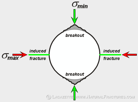
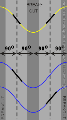
Breakouts (dark gray rectangles in Fig. 4) and induced tensile fractures form in the compressive and tensile quadrants on both sides of the wellbore. Arrows (Figures. 3 & 4) indicate the centers of the tensile and compressive quadrants. Black lines on colored sine waves (Fig. 4) indicate induced tensile fractures that are inclined to the wellbore. When the minimum principal stress is perpendicular or nearly perpendicular to the wellbore: When the minimum principal stress is inclined to the wellbore: If the tensile fractures form ahead of the bit, then they may be present on both sides of the wellbore (black lines on yellow sine wave). More commonly these fractures develop behind the bit so that separate fractures develop independently on both sides of the wellbore (black lines on blue sine waves) because the two sides of the well are mechanically decoupled. |
CONTENTS
The relationship between earth stress and wellbore stress |
|
|
The three principal stresses (colored arrows) define a triaxial ellipsoid,
which can be represented by the three stress ellipses in the principal planes,
as shown. This figure shows a thrust-faulting regime, in which the minimum
principal stress is vertical. Wells fail in response to the stresses in
the wellbore-perpendicular plane. Wells drilled parallel to one of the principal stress axes are special cases because the wellbore-perpendicular plane is a principal plane. A principal plane is a plane that contains two of the three principal stresses. As shown in the diagram, there are three such special cases. In these cases the breakouts reflect the orientation of either the minimum or intermediate principal stress, as shown by the dashed lines. |
Figure 5.
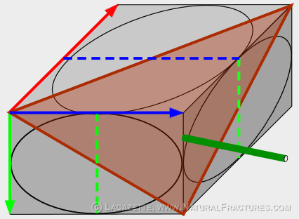
| A well drilled at a general angle (dark green cylindrical line) fails in response to the stresses in the wellbore-perpendicular plane (brown). The stresses in this plane are a complex combination of all three principal stresses. The shape and orientation of the stress ellipse in this plane is given by slicing the 3-dimensional stress ellipsoid in this orientation. |
CONTENTS
A common mistake: Equating breakout orientation with principal stress orientation |
|
| Colored arrows indicate the three principal stresses. Light gray parallelogram represents a horizontal plane. Dashed arrow represents the breakout axis. A wellbore (dark green cylindrical line) fails in response to the stress-state in the borehole-perpendicular plane (brown ellipse.) To a first approximation, the breakout axis (dashed double-headed arrow) indicates the orientations of the minimum and maximum stress components in this plane (double arrows). The breakout azimuth (gold line) is the horizontal component of the breakout axis orientation. |
Figure 6.
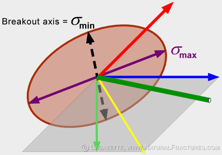
| Note that the breakout azimuth is different
from the principal stress azimuths. In the case shown here, the minimum principal
stress is vertical so it has no horizontal component and the breakout
azimuth reveals nothing about its azimuth. The breakout azimuth is at a high horizontal angle to both the intermediate and maximum principal stresses, but shows no obvious relationship to them. Because hydrofracs always run perpendicular to the minimum stress once they have propagated a few wellbore diameters, any hydrofracs driven from this well will run horizontally, not perpendicular to the breakout azimuth. The drawings shown in this discussion are based on the first-order assumption that breakout orientations are strictly related to the orientation of the well relative to the stress field in the rock volume around the wellbore. In detail, the relationship between the breakout azimuth and principal stress orientations is complex and also depends on the orientation of bedding, the rock properties, and the rock and wellbore fluid pressures because these affect the stress state of the wellbore wall. |
CONTENTS
Why are these mistakes so common? |
|
HISTORY: These misconceptions have the following origins:
|
|
Go to Page 1.1.3 to learn more about regional earth-stress regimes. |
|
Copyright © 2000 - 2017 • Alfred Lacazette • All Rights Reserved
